
Structure
of Lesson
7.1
Objective
7.2 Introduction
7.3
Random Access memory
7.3.1
Capacity of RAM
7.3.2
Types of RAM
1. DRAM
2. SRAM
7.4 ROM
7.4.1 Types of ROM
1. Masked ROM
2. PROM
3. EPROM
7.5 Processor
Registers
7.6 Processor
cache
7.7 Summary
7.8 Glossary
7.9 Suggested Answers to SAQ
7.10 References/Bibliography
7.11 Suggested Readings
7.12 Model Questions
7.1
Objective
Similar
to the brain of human beings, the brain of computer i.e. Central processing
unit also has the memory to store and recall the tasks. The primary memory of
computer is used continuously from the very moment it is switched on. The aim
of chapter is to explain the concept of primary memory, its need and types in
detail.
7.2 Introduction
Primary
storage (internal memory), often referred to simply as memory, is the only one
directly accessible to the Central processing unitthat’s why it is called Primary.
The CPU continuously reads instructions stored there and executes them as
required. Any data actively operated on is also stored there in uniform manner. Primary memory is the main memory and a
computer cannot run without it. It is installed as a chip mounted on the
motherboard.
Thus
primary memory can be classified as:
1.
RAM (Random Access Memory) – Volatile memory that is temporarily used to store
data and instructions during program
execution.
2.
ROM(Read Only Memory) - Non-Volatile memory required by the computer during
booting up.
3.
Processor registers –The local memory of processor used to hold most frequently
used data, instructions and state values.
4.
Processor cache- Small, fast memory which is used to store replicas of
instructions and data which if assessed from main memory, would cause delay.
The
section 2.3 explains Random access memory with its types covered in various sub
sections. Read only memory and its types are covered under section 2.4. The
sections 2.5 and 2.6 cover Processor registers and processor cache respectively.
Memory Hierarchy
The
computer memory needs to be organized in a hierarchy where slower and larger
memories supplement faster and smaller ones. The processor registers occupy the
top most place in hierarchy followed by the faster, expensive and small memory
module called processor cache. On the next rung are larger and relatively slow
main memory parts. The main memory is followed in hierarchy by larger and much
slower secondary magnetic storage memory devices like hard drives.


7.3 RAM (Random Access Memory)
Random
Access memory commonly abbreviated as RAM is a type of primary memory that
allows data access in any random order in contrast to sequential access
memories such as magnetic tapes, CDs, DVDs, hard drives etc. Random Access
memory is also called scratch-pad memory and is used extensively in digital
computation systems. The primary function of a scratch-pad memory is to reduce
the overall response time of the computation system by reducing the systems
dependence on a relatively slow secondary memory unit for many operations. Central
processing unit can read and over write data and instructions stored in RAM. All
the programs and data that need to be executed must be transferred to RAM from
external storage device. The storage space in RAM always has the priority so
after the execution of a program the space is reallocated to another program
waiting for its execution. The pieces of data or program instruction stored in
specific portions of RAM are called addresses.The address allows a program to
be located, accessed and processed much like the addresses in real world.

RAM
The
earliest known form of random access memory was William’s Tube. The William’s
tube was based on a cathode ray tube in which an electron beam was used to read
and write data in form of electrical spots. Its capacity was limited to a few
thousand bits of data. William’s tube was succeeded by Magnetic-Core memory
which relied upon an array of magnetized rings with each ring storing onebit of
data. The magnetic-core memory was replaced by modern solid state integrated
circuit chips mounted on motherboard of digital computer. Today RAM is
available in the form of plug in modules and integrated circuits. The small
circuit boards containing memory IC’s and having input output lines connected
to edge connector are plug-in modules. Memory slots on motherboard hold memory
modules. There are three types of memory modules: SIMMs, DIMMs and RIMMs. SIMM
stands for single inline memory module, DIMM stands for double inline memory
module and RIMM stands for Rambus inline memory module. SIMM functions by
connecting pins on opposite sides of circuit board whereas in DIMM the pins
form double set of contact by staying individual. More than one memory chips
can be used to build the RAM for more powerful systems.
7.3.1 Capacity of RAM
The
computer can only understand the information in terms of 0’s and 1’s. These are
called binary digits. Each binary digit is called a bit and the group of eight
binary digits forms a byte.
The
most important characteristic of computer memory is its capacity which for
internal memory is expressed in form of bytes (1 byte = 8 bits) or words.Most
of the chips contain a few thousand bits so their memory capacity is expressed
in kilobits(Kb) or mega-bits (Mb) where b is used to denote bits not bytes. The
word size of the chip is also an important measurement. It is the “natural”
unit of organization of memory. The number of bits that can be simultaneously
processed by a computer is called word length. The size of the word is equal to
number of bits used to represent an integer and to the instruction length.A
word consists of one or more bits. This number of bits accessed by processor is
determined by the word size of a chip.A notation used to indicate the total
capacity of chip is as follows:
N
x s (where N represents total number of words and s is total number of bits per
word)
8,
16 and 32 are commonly used word lengths. Further each word in a chip has a
unique address. This address is used directly by central processing unit to
read or write data to a specific memory location.
7.3.2 Types
of RAM
The
three basic building blocks of RAM are an array of memory cells (each of which
is capable of storing one binary digit), an address decoder and a read /write
control logic. The types of RAM are classified based upon the nature of rows
and columns of memory cells. The classification is as follows:
1. DRAM
Dynamic
Random access memory is abbreviated as DRAM. It is a class of volatile
semiconductor memory which allows data to be read and written to the storage
locations of device in a non-linear manner. It is widely used as main memory in
digital computer equipments. Each bit of data in DRAM is stored in a separate
capacitor in an IC. The two values of a bit i.e. 0 and 1 are represented by two
states of capacitor which can either stay charged or discharged. The DRAM chips
need to be constantly refreshed or re-energized in order to prevent data loss
because the charge leaks from capacitor with time and it slowly discharges thus
fading the original information stored in it. Because of this constant refresh
requirement it is called dynamic RAM. During the refreshing process the data is
read and rewritten back in the respective locations. The density and memory
capacity for DRAM varies greatly. As only one capacitor or transistor or
transistor is needed to store one bit of information and they are extremely
small in size, this makes millions of them fit onto a single DRAM chip thus
increasing its density.
There
are many variants of basic DRAM chip available in the market. Most of them are
much faster than the original DRAM. One of these is synchronous DRAM (SDRAM).
These chips are synchronized to the system clock and runs at the full speed of
processor bus without any wait cycles. This performs best for serial transfer
of large blocks of data for word processing and multimedia. The refresh
counters of SDRAM determine when to issue refresh commands to the SDRAM. An
internal refresh cycle is generated when SDC refresh counter times out and an auto
refresh command is issued to all the SDRAM banks.
One
of the limitations of SDRAM is that it can transfer data only once per bus clock
cycle. To overcome this limitation a newer version of SDRAM is available called
double data rate SDRAM (DDR SDRAM). It can send data to a single clock cycle
twice, once on the rising edge of the clock pulse and another on the falling
edge. This makes it much faster than SDRAM and provides a direct path to double
the memory bandwidth of an application thus increasing the peak performance of
an application. Subsequent versions of DDR SDRAM are named as DDR2 and DDR3
which raised the data transfer rate by 4x and 8x respectively.
2. SRAM
Static
random access memory is abbreviated as SRAM. SRAM uses traditional flip- flop
logic- gate configurations to store the binary values.This makes flip flop
circuit as its memory cell. Each bit in SRAM needs four transistors for storage
which form two cross coupled inverters. This forms a storage cell having two
stable states each of which either denotes 1 or 0. Two additional access
transistors control access during read and write operations. A static Ram holds
data as long as power is supplied to it.An SRAM cell can be in three states:
Standby, Read or Write. During standby state the circuit is idle and cell is disconnected
from bit lines.During read or write operation the data, address and control
signals need to be asserted in a specific order and they need to be stable for
certain amount of time during operation. It needs no refresh circuitry as needed by
Dynamic RAM. This makes it much faster and more reliable than DRAM chips as no
additional refresh circuitry is required. It is much more expensive and can
hold less data as compared to DRAM. It is used for CPU caches and CPU register
files due to its fast speed. The SRAM can be classified broadly as synchronous
SRAM and asynchronous SRAM. Synchronous SRAMs have their signals synchronized
with system clock whereas in asynchronous SRAM the signals are independent of
system clock frequency. The asynchronous SRAM is faster and is appropriate as
main memory for cache-less embedded processors. The data in and data outs for
asynchronous SRAM are associated with clock signals.
7.4 ROM (Read Only Memory)
Read
only memory abbreviated as ROM is a type of primary memory used to hold the start-up
and boot information in computer. In contrast to Random access memory (RAM) the
instructions written in ROM are non-volatile i.e. they don’t lose their state
when power is switched off and are thus permanent.As soon as ROMcircuitry receives
power, the bootstrap loader program is initialized. The bootstrap program
further gives instructions to the core operating system programs to load into
RAM. The system level software like BIOS(Basic input output system) needs to be
stored in a read only format as they are less likely to be updated and changed
during their lifetime. So this information is permanent and needs to be
retained even after power is witched off because during booting the volatile
memory is empty and cannot hold the start-up routines. Therefore ROM is used to
solve this purpose.
The
information in read only memory is programmed during manufacture process. The
presence or absence of transistor in a specific location is achieved by
programming the memory at various points in the fabrication process. If current
is present in a transistor, it is counted as one and the absence of current is
denoted by 0. So memory cell in ROM is a single transistor. ROM’s are the
densest semiconductor memories and require only a read operation.
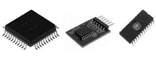

Various types of ROM chips
7.4.1 Types
of ROM
The
ROM chips can be classified according to the method used to burn data to them
and the number of times the data can be re-written to them. The classification
is as follows:
1. Masked ROM
The
masked ROM chip is hardwired during fabrication process using processing masks.
In this chip bit pattern is permanently recordedby masking and metallization
process. Mask is a photographic negative used to store required data on ROM
chip. A different mask is needed to store different sets of information. The
contents of these types of chips are specified before its production so that
this data can be used to arrange memory cells inside the chip.
2. PROM (Programmable ROM)
Programmable
ROM is a type of Read only memory that can be programmed by a user using a
programming device called PROM programmer. The PROM programmer creates or
destroys the internal links in form of fuses and antifuses by applying correct
voltage for specific amount of time to permanently write the data to chip.If
the fuse is blown then it does not allow any connection to be established
therefore a zero is stored. With a fuse intact the logic number of one is
stored. So the chip can be programmed only once but can be read many times.
PROM chip is sensitive to static electricity as it can cause fuses to burn out
and thus change the essential bit pattern from 1 to 0. PROM is much more
economical than masked ROM.
3. EPROM (Erasable PROM)
Erasable
programmable ROM is much like PROM but with a difference that it can be erased
and reprogrammed as many times desired. So this makes it an indispensible
product for software development and testing. After programming it also holds
the stored data indefinitely and is non-volatile.
Based
on the way to erase and reprogram the chip it can be of two types which are UV
EPROM and EEPROM. UV EPROM stands for
ultra violet erasable EPROM which can be erased by shining ultraviolet light on
transparent window on chip meant for the same purpose. The memory cell in UV
EPROM is MOS transistor with a floating gate which is normally off but can be
turned on by passing a programming pulse in form of a beam of electrons a t
floating gate. These electrons are trapped in floating gate and stay like that
even after power is witched off. But the
photo current of UV radiation removes the stored charge and puts the floating
gate back to off state thus erasing whole data non- selectively. Electrically
erasable PROM differs in structure and function from UV PROM in following ways.
The memory cell in EEPROM is slightly modified as compared to UVEPROM. It has
an oxide coating layer above the memory cell. The programming pulse of high
voltage with reversed polarity can erase the charge in floating gate region.
The data can be selectively erased in EEPROM chip and the time required to
reprogram the chip is also much less than that of UV EPROM chips. EEPROM is
less dense and more expensive as compared to UVEPROM. It is mostly used to
store programmable instructions for devices like printers. Flash memory is a
special type of EEPROM that is used by most computers to hold start-up
procedures and data. It can be erased and reprogrammed in blocks in contrast to
programming at byte level in most EEPROMs.
The
interaction between RAM, ROM and CPU can be explained with above diagram.
7.5 Processor registers
The
processor registers act as processor scratchpad to store information
temporarily to execute various tasks. They are basically a small amount of
storage which can be addressed by CPU.Accessing the data stored in registers is
much quicker than accessing memory so the most often accessed data is put in
these registers by optimized code. Processor registers are at the top of memory
hierarchy. In general the size of all the processor registers is same. A 32 bit
processor has all the registers of 32 bit wide and the registers of 64 bit
processor are 64 bit wide. Some of the registers are used internally by
processor and some of them can be manipulated by programs running on computer.
The contents of one register may be added to the contents of another one.
This classifies
the registers as general purpose registers and special purpose registers. The
number of processor registers varies according to the type of processor. Some
of the processors have about 10 of them whereas others may have more than 100.
A type common to all the processors is program counter register. The next
instruction to be processed is marked by PC. It is also called instruction
pointer. Status register is also a type of special purpose register that holds
information about state of processor. General purpose registers store both data
and addresses which are used by instructions that directly access RAM.
7.6 Processor cache
Cache
memory is used to increase the performance of a system by storing the
frequently used data and instructions which can later be accessed by processor
for a specific task. Cache is much faster than RAM and much expensive too. The
access time of cache memory is less than that of main memory by a factor of 5. The
data from frequently used RAM locations can be stored in cache for later use.
If a copy of data remains in cache then the operation can be completed much
more quickly as compared to reading the data from main memory.
The two terms are frequently used
pertaining to availability of data in cache. If a reference of required data is
found in cache then it is called cache hit but if the reference is not
available in cache then it is termed as cache miss.
The
Cache is classified into two types:
·
L1 (Level 1) cache
·
L2 (Level 2) cache
L1
cache is integrated within the processor whereas L2 cache is located on motherboard
outside the processor but near to it. L1 cache has very small capacity to store
data ranging from 8 KB to 128 KB whereas L2 cache has capacity ranging from 64
KB to 16 MB. Larger caches have lower miss rate but tend to be slower than
smaller ones. Processor first looks data in L1 cache but if it misses then L2
cache is accessed. If L2 cache also misses then main memory is accessed.
7.7 Summary
Out
of all the types of memories available to a digital computer the primary memory
also known as main memory is directly accessible to the processor and holds
current data and instructions. The primary memory is further classified as RAM
(Random access memory) and ROM (Read only memory). Each of them plays its own
role in computer operation. Whereas RAM is volatile ROM is non-volatile
storage. The RAM Rom and processor interact with each other to execute all the
tasks assigned by user. The RAM can be static or dynamic and ROM can be
programmed erased and reprogramed thus classifying it as PROM and EPROM.
Processor has its own internal memory too which acts as its scratchpad. These
are processor registers and cache. Out of all the memory types the processor cache
is fastest and most expensive and bridges the speed gap between processor and
primary memory. Thus all kinds of primary memory help to execute instructions
in a more efficient and reliable way.
7.8 Glossary
Primary
Memory:
Main memory accessible directly by processor. Stores data temporarily
and is faster than any other type of memory.
Bit
:Smallest unit of data represented as 0 or
1
Byte:
Combination of 8 bits
RAM:
Random access memory. Used to access data by processor quickly and randomly
based on addresses. Data is lost as soon as power is witched off hence making
it volatile.
ROM:
Read only memory. Non volatile memory that holds start-up routines for a system
DRAM:
Dynamic random access memory. Uses capacitor states to store data
SRAM:
Static random access memory. Uses flip flop circuits to store data.
PROM:
Programmable Read only memory. Programmed during fabrication.
EPROM:
Erasable programmable read only memory. Can be programmed many times by user
using ROM programmer.
EEPROM:
Electrically erasable programmable read only memory. Can be written many times
and erased electrically or using UV radiation
Cache
memory: Fastest, smallest and most expensive type
of memory built for temporary storage of data by processor.
7.9 Suggested Answers to SAQ
Question 1: Explain the
memory hierarchy for digital computers
The
computer memory needs to be organized in a hierarchy where slower and larger
memories supplement faster and smaller ones. The processor registers occupy the
top most place in hierarchy followed by the faster, expensive and small memory
module called processor cache. On the next rung are larger and relatively slow
main memory parts. The main memory includes RAM which is volatile storage
medium.The main memory is followed in hierarchy by larger and much slower
secondary magnetic storage memory devices like hard drives.
Question 2: Explain the
purpose of RAM as primary storage device.
Random
Access memory commonly abbreviated as RAM is a type of primary memory that
allows data access in any random order in contrast to sequential access
memories such as magnetic tapes, CDs, DVDs, hard drives etc. Random Access
memory is also called scratch-pad memory and is used extensively in digital
computation systems. The primary function of a scratch-pad memory is to reduce
the overall response time of the computation system by reducing the systems
dependence on a relatively slow secondary memory unit for many operations.
Central processing unit can read and over write data and instructions stored in
RAM. All the programs and data that need to be executed must be transferred to
RAM from external storage device. The storage space in RAM always has the
priority so after the execution of a program the space is reallocated to
another program waiting for its execution. The pieces of data or program
instruction stored in specific portions of RAM are called addresses. The
address allows a program to be located, accessed and processed much like the
addresses in real world.
Question 3: Why is ROM
referred to as Non- volatile memory? Explain its types.
Read
only memory abbreviated as ROM is a type of primary memory used to hold the
start-up and boot information in computer. In contrast to Random access memory
(RAM) the instructions written in ROM are non-volatile i.e. they don’t lose
their state when power is switched off and are thus p The ROM chips can be
classified according to the method used to burn data to them and the number of
times the data can be re-written to them. The classification is as follows:
Masked
ROM
The
masked ROM chip is hardwired during fabrication process using processing masks.
In this chip bit pattern is permanently recorded by masking and metallization
process. Mask is a photographic negative used to store required data on ROM
chip. A different mask is needed to store different sets of information. The
contents of these types of chips are specified before its production so that
this data can be used to arrange memory cells inside the chip.
PROM
(Programmable ROM)
Programmable
ROM is a type of Read only memory that can be programmed by a user using a
programming device called PROM programmer. The PROM programmer creates or
destroys the internal links in form of fuses and antifuses by applying correct
voltage for specific amount of time to permanently write the data to chip. If
the fuse is blown then it does not allow any connection to be established
therefore a zero is stored. With a fuse intact the logic number of one is
stored. So the chip can be programmed only once but can be read many times.
PROM chip is sensitive to static electricity as it can cause fuses to burn out
and thus change the essential bit pattern from 1 to 0. PROM is much more
economical than masked ROM.
EPROM
(Erasable PROM)
Erasable
programmable ROM is much like PROM but with a difference that it can be erased
and reprogrammed as many times desired. So this makes it an indispensable
product for software development and testing. After programming it also holds
the stored data indefinitely and is non-volatile.
Question 4: What the
storage elements inside processor and how do they work?
The
storage elements found inside processor are processor registers. The processor
registers act as processor scratchpad to store information temporarily to
execute various tasks. They are basically a small amount of storage which can
be addressed by CPU. Accessing the data stored in registers is much quicker
than accessing memory so the most often accessed data is put in these registers
by optimized code. Processor registers
are at the top of memory hierarchy. In general the size of all the processor
registers is same. A 32 bit processor has all the registers of 32 bit wide and
the registers of 64 bit processor are 64 bit wide. Some of the registers are
used internally by processor and some of them can be manipulated by programs
running on computer. The contents of one register may be added to the contents
of another one.
7.10 References/Bibliography
1) Alexander
John Anderson,Foundations of Computer TechnologyAnil K. Maini, DIGITAL
ELECTRONICS: PRINCIPLES AND INTEGRATED CIRCUITS
2) Anderson,
Christa, The Definitive Guide to Citrix MetaFrame XP
3) A.P.
Mathur, Introduction to Microprocessors
4) Barry
G. Blundell, Nawaz Khan, AboubakerLasebae, MuthanaJabbar, Computer Systems and
Networks
5) David
Buchanan, The Treasure of Auchinleck: The Story of the Boswell Papers
6) David
Money Harris, Sarah L. Harris, Digital Design and Computer Architecture
7) Gary
Shelly, Misty Vermaat, Discovering Computers 2011: Complete
8) Gary
Shelly, Misty Vermaat, Discovering Computers 2009: Brief
7.11 Suggested Readings
1) Anita
Goel, Computer Fundamentals
2) B.
Ram, Computer Fundamentals: Architecture and Organisation
3) P.K
Singh, Basics of computer
7.12 Review Quiestions
- Explain
the types of RAM?
- Describe
processor cache and its need?
- Explain
DIIM?
- How
is capacity of memory measured?
Structure
of lesson
8.1
Objective
8.2
Introduction
8.3
Sequential access storage devices
8.3.1 Non-magnetic type
8.3.2 Magnetic type
8.4
Direct Access storage devices
8.4.1 Magnetic type
A)
Hard disc
B)
Floppy disc
C)
Zip disk
8.4.2 Optical type
A)
Compact disc
B)
DVD
C)
Blu-Ray discs
8.4.3 Electronic type
A)
Solid state drives
B)
Flash drives
8.5 Summary
8.6 Glossary
8.7 Suggested Answers to SAQ
8.8 References/Bibliography
8.9 Suggested Readings
8.10 Model Questions
8.1 Objective
Modern
computers process large amounts of data and the results are often needed to be
stored for future reference or further processing. This is where secondary
memory comes into picture. The present chapter explains different available
secondary memory types, their classification and working principles.
8.2 Introduction
Secondary
storage or auxiliary memory is not directly accessed by a processor. Primary
memory sits between secondary memory and CPU. Secondary memory holds
information until it is deleted or overwritten regardless if the computer has
power, thus secondary memory is computer memory that is non-volatile and
persistent in nature. This characteristic makes such storage fit for storing
data for future retrieval. Secondary memory is slower than primary but has
substantial storage capacities, ranging from some MBs to several TBs of storage
space. Normally hard disk of computer is used as secondary memory but this is
not portable so there are many other secondary storage media in use.
Primary Memory
|
Secondary Memory
|
Directly accessible
by CPU
|
Accessible to CPU
only via primary memory
|
Volatile
|
Non-Volatile
|
Smaller but Faster
|
Larger but Slower
|
Price per unit
storage is high
|
Price per unit
storage is least
|
Examples are RAM,
ROM, Processor cache etc.
|
Examples are Hard
disks, USB drives, CDs etc.
|
Data from a secondary
storage device can be accessed in two manners, direct access and sequential
access. The type of access forms the basis of their classification.
1.
Sequential access secondary storage devices permit accessing a record in one
particular order i.e. arrival at a certain record is preceded by sequencing
through preceding records. Due to varying number of records before any given
record, access time varies as per location. Magnetic tape is the best example
of storage device which employs sequential access.
2.
Direct access secondary storage devices permit accessing a record directly as
each record has discrete location and unique address. Since each record has a
unique address, access times for each record are approximately equal. Hard disk
drives, CDs, DVDs, USB drives all use direct access method.

Detailed
classification of secondary storage devices is given in the following diagram.
8.3 Sequential Access Storage Devices (SASD)
Data
from sequential or serial access storage devices can be accessed in the order
in which it was written. To reach a particular record in such devices a lot of
data is read and discarded before the required record is encountered. SASD are
not suitable for storing data that is updated often.
8.3.1 Non Magnetic or Paper Type
Punched
tape or punched cards are common non magnetic SSAD. Multiple vertical channels
are used and a single character or code is punched as a pattern of bits in each
line. Data is thus represented by the presence or absence of a perforation at a
particular location. A row of narrower holes that are always punched in middle
serve to feed the tape. The preparation of paper input tapes is sometimes
called as key-boarding. In this, operator is presented with a copy of a program
or input data. The operator then punches a number of holes into the tape. The
tape punch devices resemble a typewriter, and the keyboards of these tape
punches contain letters and symbols. The character selected is punched into the
tape corresponding to each key depression in binary form and the tape moves on
to the next line. Tape punches are also able to read a perforated tape and to
type copy from it. Optical readers that generate pulses on passage or blocking
of light are used to read data from paper tapes.
Mechanical damage is biggest drawback for
paper tapes but they serve well in conditions of high magnetic fields where
magnetic tapes cease to perform. Paper tapes can even be manually edited by cut
paste method. Now-a-days paper tapes are an obsolete technology.
8.3.2 Magnetic Type
Magnetic
tape is a common magnetic type SASD. Magnetic tape is commonly used in audio or
video cassettes. Reels or cartridges of magnetic tape were used for storing
data from as early as 1951. Magnetic tapes are manufactured by coating a thin
layer of iron oxide on Mylar film generally 2000-3000 feet long. A 2400 feet
long tape can store about 18 million characters.
Tape
is horizontally divided into 7-9 tracks and vertically into frames. Each frame
stores one byte of data. Inter-record gaps separate blocks of data on a tape.
The tape is rolled over
spools. Read/Write operations on tape are carried out by a read/write head
consisting of ring shaped core with a narrow gap. A coil over the core varies
magnetic field over tape passing through gap causing change in magnetization
state of iron oxide coating of tape. The data over tape can be stored in analog
form by varying the current signal or in digital form by keeping current
constant but switching it on and off.
Even though tapes inherit the drawbacks of SASD and are
prone to damage by dust, they are still in use because of their low cost and
lesser power consumption. Tapes are in fact the most used media for data
archiving. Tapes are categorized on basis of their width. Commonly used are half
inch and quarter inch wide magnetic tapes.
8.4 Direct Access Storage Devices (DASD)
Direct
access storage devices allow random access to any stored record. This allows
lesser time consumption as extensive searching for a particular record is
eliminated. Direct access devices are the most flexible storage devices as they
can contain sequential, partitioned and direct data sets. DASDs are best suited
to store high activity data that needs to be updated often.

8.4.1 Magnetic Type
Most
of the present DASDs are based on magnetic recording technology. After four
decades of development, this technology has become very refined and
predictable. The basic principle of writing on a magnetic surface is changing
the magnetic polarity from south to north or from north to south, as the case
may be. Magnetic disks allow higher data
transfer rates than tapes and are portable more rugged.
A. Hard Disk
Hard
Disk is the most used DASD. Hard disk is a fixed disk i.e. the disk is not
removable from the drive. The hard disk and Hard Disk Drive (HDD) are sealed in
a single unit. Hard disk has much higher capacity than floppy disk. This is
mainly possible because of two main factors, firstly the data in hard disk is
packed more closely due to higher spinning speed permitting use of smaller
magnetic charges and secondly, they have large number of disks or platters that
are grouped together and are mounted on a common drive to form a disk
pack. Large capacity hard disks may have
12 or more of such platters. Platters are made of non magnetic material like
aluminum or other metals or metal alloys instead of plastic. The data is stored
on these platters covered with a magnetic coating. Data is recorded by
magnetizing the magnetic material coating. The direction of magnetization
represents either a '0' or a '1'.
Parts
of hard disk
1.
Spindle
2.
Access arms
3.
Read/Write head
4.
Disk pack
Platter
surfaces of hard disk are divided into concentric circles called tracks. Each
track is further divided into a number of fixed length physical blocks called
sectors. Sector is the smallest unit of data for transfer. Hard disk platter
generally has 800 tracks and has 54 or more sectors per track. 512 bytes of
data is stored per sector. Same single corresponding track over all hard disk
platters of a disk pack is called a cylinder. Some operating systems like
Windows merge several sectors to form clusters and use them as basic unit of
memory for read/write operation. Nowadays, hard disks that can store up to 5TB
of data are available. Hard disk is the key secondary storage device of
computer as the operating system is stored on the hard disk. Portable external
hard disk drives are now available which can be attached to the USB port of the
computer. They come in the storage capacities of 80 GB to few TBs.
Storage
capacity of one surface = No. of tracks x No. of sectors x bytes per sector
Storage
capacity of the disk pace = Storage capacity of one surface x No. of surfaces
Number
of cylinders = No. of tracks per surface
Transfer
rate = No. of bytes per track x Rotational speed
Each platter has its own
read/write head for each surface over which data can be written. The read/write
head of hard disk does not touch the platter; instead it glides on an air gap
0.000001 inch thick during read/write operation. In fact if head touches the
platter, hard disk crashes. Read/write heads use magneto-resistance phenomenon
to sense the change in magnetic field. The electrical resistance of the head
changes as per the strength and orientation of the magnetism on the disk. A
typical desktop hard disk rotates at 7,200 revolutions per minute and has an
access time of 9-14 milliseconds.
The
time to access a record on a hard disk consists of 3 components
1.
Seek Time
2.
Rotational Latency Time and
3.
Data Transfer Time
Seek
time is the time taken to position the read/write head at the desired track on
the disk. It involves motion of read/write head. Seek time will be maximum if
position of head is on outermost track an innermost track is to be read and
vice-versa. Rotational Latency Time is the time taken to position the
read/write head at the desired sector of the track seeked. As sectors are
arranged circumferentially over track, latency time depends on the speed at
which platters rotate. Rotational delay averages to time taken for half
revolution. Data Transfer Time refers to time taken to read off data from disk
after a particular sector has been identified. It depends upon density of
stored data and rotational speed of the disk.
Formatting
In
order to use a disk, it has to be formatted. Formatting a disk can be compared
to opening a library, wherein before storage of books, bookshelves and catalog
system need to be in place. Hard disks commonly come formatted by the
manufacturer. The process consists of
three parts
1.
Aligning magnetic particles and dividing disk into tracks and sectors termed as
low level formatting.
2.
Partitioning or grouping adjacent cylinders into partitions. All cylinders can
be grouped into a single partition but to run multiple operating systems, two
or more partitions need to be created.
3.
This process involves generating a new fileystem for the operating system and
is called high-level/logical formatting. The operating system uses this file
system to store directory structure. Additionally cluster size is also defined
by file system that defines smallest subdivision of the disk used by OS for its
index. A table at sector 0 of disk is also created by OS to store locations of
files. Commonly used file systems used in logical formatting of magnetic disks
are FAT, NTFS, HFS, UFS, ext2, ext3.
B. Floppy Disk
FloppyDisk
is a small sized, round, thin single disk made of Mylar plastic coated with
magnetic oxide material and enclosed in square rigid plastic jacket to protect
it from dust and smudges. Data is stored on the magnetic coating by means of
magnetized spots. A floppy disk was ubiquitous direct access secondary storage
medium for micro and mini computers but hard disks have eventually replaced
them. Floppy Disk Drive (FDD) serves as drive for floppy disk. Floppy disk
drive serves as a device to hold, spin and perform read/write operations on the
disk. The floppy disk is inserted into the FDD to read/write data to it. While
data is being read/write, the floppy drive rotates the disk at a speed of about
360 rotations per minute and a read/write head is positioned by a motor to
read/write over the floppy disk surface. The disk should not be removed when
the access light on drive is on.
A floppy disk can be single or
double sided. Double sided floppies allow data to be written on both sides.
Density of magnetic material coating also varies as single density and double
density.
Prominent visible
features on a Floppy disk:
1.
Write protect notch-Allows to prevent the diskette from being written to
accidently.
2.
Index hole-Used to recognize the starting sector of any track.
3.
High capacity hole-Used to recognize whether floppy is high capacity.
4.
Drive hole-To allow a spindle to lock the floppy so that it can rotate
5.
Sliding cover-A spring loaded shutter to expose coated mylar film to read/write
head when inserted in drive.
The magnetic coating on a new
floppy is not organized and hence it cannot be used without formatting it. The
process of formatting a disk involves aligning magnetic particles to create a
set of magnetic concentric circles called tracks. Tracks are further divided
into sectors.
Salient
features of floppy disks are:
1.
They are portable.
2.
They can be write-protected
3.
They are small and cheap
4.
They provide slower access than a hard disk.
5.
They have less storage capacity.
6.
They are available in two basic sizes-5-1/4 inch and 3-1/2 inch
The
5-1/4 inch disk can store 360 KB to 1.2 MB of data. On the other hand the 3-1/2
inch disk has capacity of 400 KB to 1.44 MB.
Difference B/W floppy
disk and Hard disk
Floppy Disk
|
Hard Disk
|
Disk
can be separated from drive
|
Disk
and drive are integral
|
Contains
single disk
|
Contains
multiple platters
|
Read/write
head contacts the disk
|
Read/write
head glides over platter
|
Small
storage space in order of few MBs
|
Massive
storage space in order of several GBs
|
Normally
have 135 tracks per inch
|
Normally
have hundred thousand plus tracks per inch
|
A
floppy disk being open in nature is prone to damage from humidity or dust
|
The
sealed nature of hard disks protects them from dust scratches or humidity
|
Recording
density varies
|
Uniform
recording density
|
C.
Zip Disk
In
terms of storage and technology in magnetic DASDs, zip disks lie between floppy
and hard disk. Zip disks have capacity ranging from 100 to 750 MB. Higher
capacity in zip drive is achieved by a combination of two factors, first it has
a better magnetic coating that allows read/write head to be about on tenth of
that used in a floppy, and second a smaller head permits writing 2000+ tracks
per inch. Moreover the head in zip disk is similar to hard disk in the sense
that it doesn’t touch the disk. Zip
disks are available as a complete unit with drive, power supply, connection cord
and software for operating it.
8.4.2 Optical Type
Optical
disc employs optical technology in form of laser beams to read and write data
optically. The optical discs are available as thin, circular discs made of
plastic (polycarbonate substrate) covered with coatings of another materials to
store data and to prevent damage to disc. The optical disc has only single
spiral track unlike magnetic discs which have multiple spiral tracks. The
tracks are further divides to sectors for the purpose of data organization.
The
binary data on optical disc is recorded in form of Lands and pits with help of
a laser beam. Land has binary value of 1 due to reflection when read whereas
pits have binary value of 0 due to lack of reflection when read. The pits and
lands themselves do not directly represent the zeros and ones of binary data.
Instead, non-return-to-zero, inverted encoding is used: a change from pit to
land or land to pit indicates a one, while no change indicates a series of
zeros. There must be at least two and no more than ten zeros between each one,
which is defined by the length of the pit. The data on optical disc can be
accessed when laser diode in optical disc drive illuminates data path while
disc spins at high speeds. The lands and pits distortthe reflected laser light
hence giving them the typical rainbow look. The optical discs can be used in
optical disc players only. The process by which the data is records onto an
optical disc is called burning. There are many programs available to burn the
discs. The standard size of optical disc is 120mm (approximately 4.7 inch).
Mini discs of 80mm are also available.
The most common use of optical discs is for
storing music, video, or data and programs.
There
are three recording types available for optical discs. These are:
Read
only types (CD and CDROM)
Recordable
(CD-R, DVD-R)
Re-
recordable (CD-RW, DVD-RW)
Each
of these is discussed in further sections.

A. Compact disc (CD)
The
Compact disc is abbreviated as CD. It is an optical disc storage format introduced
in 1982 which immediately replaces phonograph records as the primary medium for
home –recorded audio. The compact disc offered various advantages over these
records. These records had to preserve their mechanical grooves and mechanical
transport in them introduced audible artifacts, moreover this analog circuitry
was prone to ageing and temperature drift. Compact disc delivers better
performance in these areas as the data surface is embedded inside the disc
itself. No degradation is caused by repeated playing and damaging effect of
dust and surface damage is minimized.
This format was developed to store and playback only audio recordings
and was later developed to store data. Standard CD can hold upto 80 minutes of
uncompressed audio which equals roughly 700 MB (703 or 730 MB actually) data.
The
CD is made of 1.2 mm polycarbonate plastic which is covered by thin layer of
metal like aluminium. This metal layer makes the surface reflective. The lacquer
film is spin coated on metal layer for protection. The labeling is also done on
this lacquer layer. Pits are encoded in a spiral track moulded into the top of
polycarbonate layer. Each pit is approximately 100 nm deep by 500 nm
wide, and varies from 850 nm to 3.5 µm in length. The distance between
the tracks, the pitch, is 1.5 µm. The Data is read by focusing
semiconductor laser through the bottom of polycarbonate layer. The height
changes between lands and pits cause them to reflect light differently which is
measured with a photodiode.
CD-R
is recordable compact disc have blank data spiral to which a photosensitive dye
is applied. The laser changes color of dye during write operation. Over the
time the changes in physical characteristics of dye may cause permanent data
loss called disc rot. The data recording in these CD’s is designed to be
permanent. They are usually used in audio CD recorders.
CD-RW
is read and write (re-recordable) CD format which used metallic alloy in place
of dye as in CD-R. The laser alters the physical properties of alloy and thus
changes its reflectivity.
B. DVD
Digital
video disc was developed by Philips, Sony, Toshiba and Panasonic in 1995. DVD
offers greater storage capacity as compared to CD but their size is same as
that of CD.DVD-R has a capacity roughly equal to 4.37 GB. The laser used to
read and write DVD uses wavelength of 650nm as compared to 780nm for CD. DVD also comes in Read only, read write and
rewriteable formats.
C. Blu-Ray Disks
Blu-
ray disc format was developed to store high definition video resolution
(1080p).The diameter and thickness of blu-ray disc is same as that of CD and
DVDs. The storage capacity of blu ray discs is 25 GB per layer. A blue laser is
used to read the disc which allows data density to be greater as compared to
red laser used for CD and DVD because shorter wavelength can be focused in
smaller area.. They are mostly used to store video medium like feature films.
This format was developed by Blu-ray disc association. The blu-ray discs have
hard coating as it need to be scratch resistant.
Blu-ray
disc recordable, BD9, BD5, BDXL and IH-BD are some of the formats of blu-ray
discs. Blu-ray disc recordable can be recorded once and read many times. BD9
and BD5 were cost effective methods for blu-ray discs. BDXL has 100 GB and 128
GB write once data capacity whereas IHBD includes 25 GB rewritable layer and 25
GB write once layer.
8.4.3 Electronic Type
The
electronic storage media implies use of integrated circuits assemblies to store
and read data. It has no moving mechanical parts in it. They are more resistant
to shock and provide a quieter operation with less access time. The types of
electronic secondary storage devices are
·
Solid state drives
·
Flash drives
·
Memory cards and other smart media
Each
of these is discussed in following sections.
A. Solid State Drives
Solid
state drives use integrated circuits to store and retrieve data have no
mechanical components. Most of the SSDs use NAND based flash memory or RAM
chips. It meets market requirements for performance, reliability and cost
effectiveness. The NAND based flash memory can store data even when power is
switched off and hence is n on volatile. The idea behind development of SSD was
a simple fact that CPU can process data at much faster rate than hard drives
supply it. As hard drives have moving mechanical parts so it takes longer to
fetch information required and thus reduces overall performance. This
shortcoming was overcome with the invention of SSD.
The
main architecture of the SSD is based on two parts: the controller and memory.
The
controller is an embedded processor that executes firmware level code to bridge
NAND memory components to host computer. It performs many functions like Error
correcting, encryption, garbage collection, bad block mapping etc. Memory used
in SSD is non volatile NAND flash as it is cheaper than DRAM and can maintain
data without constant power supply. DRAM based SSD is used to improve
performance of those applications which may be held back by latency of flash
SSDs. These types of SSDs generally have internal battery or an external adapter
to ensure constant power supply. The SSDs do not store data in linear manner as
done by HDDs. They constantly rearrange the data while keeping track of its
locations.

A figure showing SDD and HDD
B. Flash Drives
Flash
drive s are data storage devices which consist of non volatile flash memory
with an integrated universal serial bus interface. They are most convenient to
use portable data storage medium. The motive behind invention of flash drives
in 1998 by Devmorgan was replacement of floppy disks. The capacity of USB flash
drives ranges from 512 MB to 1 TB. They are used most commonly to store, backup
and transfer data. The drive consists of a small printed circuit board carrying
circuit elements and a USB connector in an insulated plastic case. The USB
flash drives have USB 1.1 or USB 2.0 interface.
The
main components of flash drive include:
·
USB connector
·
USB mass storage controller device
·
Test points
·
NAND Flash memory chip
·
Crystal oscillator
·
Light emitting diode
Flash
memory controller is a microcontroller with small ROM chip which provides and
times signals to read and write data. USB connector provides interface to
connect to computer. Crystal oscillator provides clock signal and controls
device output. LED indicates data read, write and transfer. Flash drives use
FAT32 file system and can be reformatted several times.

8.5 Summary
A
computer can practically function without a secondary memory but it would be of
little use as no results or data would be stored for future use. This makes
secondary memory indispensible part of modern computers. In addition to this
the size of programs and operating system has moved to order of GBs due to
which cheaper alternative is needed to store them. Secondary storage device
provide a cost efficient method in conjunction with primary memory to make
modern day computers fast, efficient and able to handle large data. The advent
of floppies made computers move on from punched cards and tapes to compact
media. Eventually hard disks and optical media replaced floppies to meet
growing program and data size. Then came the era of flash memory that
eliminated the mechanical movements of hard disks and optical drives. Present
age marks the use of Blu-ray disks and Solid state drives which allow bigger
storage space and faster access times.
8.6 Glossary
- Secondary
storage: Memory that is not directly accessed by a
processor.
- Sequential
access secondary storage devices: Memory
devices that permit accessing a record in one particular order i.e.
arrival at a certain record is preceded by sequencing through preceding
records.
- Direct
access secondary storage devices: Memory
devices that permit accessing a record directly as each record has
discrete location and unique address.
- Punched
tape: A SASD made up of long paper strip perforated at
specific channels representing characters in binary form.
- Magnetic
tape: A SASD made up of iron oxide coating with
suitable dopants over Mylar film.
- Mylar: Trade
name of a plastic named Biaxially-oriented polyethylene terephthalate
- Read: Taking
data from secondary storage, converting to electronic signals and
transferring to the computer’s primary memory (RAM).
- Write-Implies copying
the electronic information processed by the computer from primary memory
to secondary memory.
- Formatting:
Process of aligning magnetic particles on a magnetic disk to create tracks
and sectors, partitioning and creating a file system for the disk.
- Track:
Platter surfaces of hard disk are divided into concentric circles called
tracks.
- Sector: Each
track is further divided into a number of fixed length physical blocks
called sectors.
- Cylinder: Same
single corresponding track over all hard disk platters of a disk pack is
called a cylinder.
- Cluster
size: Cluster size or allocation unit is the smallest
subdivision of the disk used by OS for its index.
- Burning: The
process of writing data on optical disc by using laser beam is called
burning.
8.7 Suggested Answers to SAQ
Question1: Explain the difference between
primary and secondary memory?
Answer:
Primary Memory
|
Secondary Memory
|
Directly
accessible by CPU
|
Accessible
to CPU only via primary memory
|
Volatile
|
Non-Volatile
|
Smaller
but Faster
|
Larger
but Slower
|
Price
per unit storage is high
|
Price
per unit storage is least
|
Examples
are RAM, ROM, Processor cache etc.
|
Examples
are Hard disks, USB drives, CDs etc.
|
Question2: What are Sequential access
storage devices and explain their types?
Ans: Data from sequential or serial access storage
devices can be accessed in the order in which it was written. To reach a
particular record in such devices a lot of data is read and discarded before
the required record is encountered. SASD are not suitable for storing data that
is updated often.
- Non
Magnetic or Paper Type
Punched
tape or punched cards are common nonmagnetic SSAD.Data is thus represented by
the presence or absence of a perforation at a particular location. A row of
narrower holes that are always punched in middle serve to feed the tape. The
preparation of paper input tapes is sometimes called as key-boarding. The tape
punch devices resemble a typewriter, and the keyboards of these tape punches
contain letters and symbols. The character selected is punched into the tape
corresponding to each key depression in binary form and the tape moves on to
the next line. Tape punches are also able to read a perforated tape and to type
copy from it. Optical readers that generate pulses on passage or blocking of
light are used to read data from paper tapes.
- Magnetic
Type
Magnetic
tape is a common magnetic type SASD. Magnetic tape is commonly used in audio or
video cassettes. Magnetic tapes are manufactured by coating a thin layer of
iron oxide on Mylar film generally 2000-3000 feet long. A 2400 feet long tape
can store about 18 million characters. Tape is horizontally divided into 7-9
tracks and vertically into frames. Each frame stores one byte of data.
Inter-record gaps separate blocks of data on a tape.The tape is rolled over
spools. Read/Write operations on tape are carried out by a read/write head
consisting of ring shaped core with a narrow gap. A coil over the core varies
magnetic field over tape passing through gap causing change in magnetization
state of iron oxide coating of tape. The data over tape can be stored in analog
form by varying the current signal or in digital form by keeping current
constant but switching it on and off.
Question 3: Explain the working of hard
disc drive?
Ans: Hard Disk is the most used DASD. Hard disk is
a fixed disk i.e. the disk is not removable from the drive. The hard disk and
Hard Disk Drive (HDD) are sealed in a single unit. Hard drives have large
number of disks or platters that are grouped together and are mounted on a
common drive to form a disk pack. Large
capacity hard disks may have 12 or more of such platters. Platters are made of
non-magnetic material like aluminum or other metals or metal alloys instead of
plastic. The data is stored on these platters covered with a magnetic coating.
Data is recorded by magnetizing the magnetic material coating. The direction of
magnetization represents either a ‘0’ or a ‘1’. Platter surfaces of hard disk
are divided into concentric circles called tracks. Each track is further
divided into a number of fixed length physical blocks called sectors. Sector is
the smallest unit of data for transfer. Hard disk platter generally has 800
tracks and has 54 or more sectors per track. 512 bytes of data is stored per
sector. Same single corresponding track over all hard disk platters of a disk
pack is called a cylinder.
Question 4: What do you understand by disc
burning? Explain the process for optical storage devices.
Ans:
Optical disc employs optical technology in form of laser beams to read and
write data optically. This process of writing the data onto an optical disc is
called burning .The optical discs are available as thin, circular discs made of
plastic (polycarbonate substrate) covered with coatings of another materials to
store data and to prevent damage to disc. The optical disc has only single
spiral track unlike magnetic discs which have multiple spiral tracks. The tracks
are further divides to sectors for the purpose of data organization. The binary data on optical disc is recorded in form of
Lands and pits with help of a laser beam. Land has binary value of 1 due to
reflection when read whereas pits have binary value of 0 due to lack of
reflection when read. The pits and lands themselves do not directly represent
the zeros and ones of binary data. Instead, non-return-to-zero, inverted
encoding is used: a change from pit to land or land to pit indicates a one,
while no change indicates a series of zeros. There must be at least two and no
more than ten zeros between each one, which is defined by the length of the
pit. The data on optical disc can be accessed when laser diode in optical disc
drive illuminates data path while disc spins at high speeds. The lands and pits
distort the reflected laser light hence giving them the typical rainbow look.
The optical discs can be used in optical disc players only.
8.8 References/Bibliography
- An Introduction to Direct Access Storage Devices
By Hugh M. Sierra
- Audio and Video Systems:
Principles, Maintenance and Troubleshooting By R. G. Gupta
- Basic Computation and
Principles of Computer Programming By KashiNathDey, Anita Goel, Sameer
Kumar Bandyopadhyay
- Digital Computer Fundamentals By
Bartee
- Discovering Computers 2009:
Brief by Gary Shelly, Misty Vermaat
- Fix Your Own PC By Corey
Sandler
- Foundations of Information
Technology By D. S. Yadav
- IBM Corporation (1975).
Introduction to IBM Direct-Access Storage Devices and and Organization Methods
- IBM Systems Magazine Jim Utsler
- Introduction To Computers
(Sie)By Norton
- Introduction to Information
Technology By I. T. L. Education Solutions Limited, Itl
- JCL Programming Bible (with
z/OS)
- Microprocessor-based Control
Systems.Sinha, Naresh Kumar.
- Modern Operating Systems, 2nd
Edition by Tanenbaum, Andrew (2001)
- Rudiments of Computer Science
By J.Bhattacharya
- Understanding Computers: Today
and Tomorrow, Introductory By Deborah Morley, Charles Parker
- Encyclopedia of Modern Everyday
Inventions By David John Cole, Eve Browning, Fred E. H. Schroeder
- The solid state revolution by
Andy bechtolsheim
- Architecture for a universal
serial bus-based PC flash disk, US 6148354 A
- Digital
Design and Fabrication edited by Vojin G. Oklobdzija
8.9 Suggested Readings
- Computer Fundamentals and Programming in C By J. B. Dixit
- Origins and successors of the
Compact disc: Contributions of Philips to Optical storage by Hans Peek,
Jan Bergmans, Jos van Haaren, Frank toolenaar and Sorin Stan.
- Inside solid state drives by
RinoMicheloni, AlessiaMarelli, KamEshghi
- Fundamentals
of Information Systems By Ralph Stair, George Reynolds
8.10 Model Questions
·
How
is blu-ray disc better than DVD?
·
How
does a SSD work?
·
Explain
the USB flash drive, its uses and working.
·
What
are the advantages of SSD over HDD?